
Cylinder Head Assembly Makers: How Precision Manufacturing Drives Engine Performance
2026-11-18
Every engine builder knows the truth: horsepower starts where metal meets precision. Yet the cylinder head assembly—the part that seals combustion, shapes airflow, and dictates thermal endurance—often gets treated as an afterthought until failures surface. This post pulls back the curtain on how precision manufacturing, not just exotic alloys or aggressive porting, determines whether an engine breathes clean at 8,000 rpm or falls flat under heat soak. You’ll see why tolerances measured in microns matter more than advertised flow numbers, and how a focused maker like DDR approaches the invisible details that separate a reliable head from a ticking time bomb.
The First Thing a Cylinder Head Maker Checks After Casting
As soon as the casting comes out of shakeout and cools enough to handle, the first stop is the raw deck face. Before any machining, the maker runs a hand over the gasket rail and around the valve pockets looking for shrinkage tears, sand wash, or a dull gray spot that usually means a cold shut. Those early surface clues reveal more than a coordinate measuring machine ever will, because they show how the metal actually moved through the mold.
On some lines the very first measurement is wall stock around the intake ports and bolt bosses. A quick ultrasonic probe tells whether cores shifted during the pour. If the reading drops below minimum even in one thin section, the casting gets quarantined before it can consume machine time.
Then the head is set on a surface plate with the cam side up. The maker rocks it diagonally and watches for light under the deck. That simple check catches distortion caused by uneven cooling, which no amount of seat and guide work can fix later.
How Valve Seat Runout Limits an Engine's Real Power Band
Most engine builders treat valve seat runout as a simple go/no-go measurement during a rebuild, but the truth is far less forgiving. Even a few thousandths of an inch of wobble in the seat can change how the valve closes under dynamic conditions, especially when cylinder pressure and valve spring harmonics start fighting each other near peak torque. The result isn't always an obvious misfire or leakdown failure—it's often a subtle power drop that shows up as the engine falls off earlier than the camshaft timing suggests it should.
Runout creates an uneven contact patch, which means the valve doesn't transfer heat or seat pressure uniformly. At lower engine speeds the valve may still hammer itself into a workable seal, but as rpm climbs, the valve bounces slightly on the high side of the seat. That bounce effectively shortens the real duration and lift the cylinder sees, pulling the top of the powerband down. You can see it on a dyno as a curve that noses over a few hundred rpm sooner than an identical combination with properly refinished seats.
Fixing this isn't about chasing a spec on a sheet; it's about measuring runout with the guide installed and the seat freshly cut, then using a dial indicator to confirm the needle barely moves while rotating the valve. When the seat is concentric, the valve doesn't waste energy rocking into place, and the engine holds its power longer instead of signing off early. On street engines that live in the mid-range, the difference might not show on a spec sheet. On a drag car or a road-race engine that spends its life near redline, cutting runout down to nearly zero is often the cheapest top-end power you can find.
Port Finish Decisions That Change Combustion Without a Dyno
A port finish choice usually gets treated as a cosmetic step, but the friction of the surface has a direct hand in how fuel clings, breaks up, and enters the chamber. On an intake port that sees a wet mixture, the old mirror-polish instinct often does more harm than good. Without a dyno, the most useful evidence comes from wet-flow testing with a visible dye or solvent, plus the way the engine responds after a loaded pull. If the floor of the runner stays shiny and smooth, fuel can creep along the wall in rivulets. A controlled texture, especially on the floor and around the guide boss, gives the fuel something to tumble against and keeps more of it suspended in the air stream.
The biggest decisions show up where the port changes direction. The short-side radius and the bowl blend usually want a different finish than the straight section of the runner. A dull, directional finish from a 60-grit roll can hold a thin boundary layer and reduce a sudden separation point, while an over-polished short turn tends to make the mixture stick and slide in ways that hurt throttle recovery. Without a dyno, you compare the carbon trace left on the back of the intake valve and the roof of the port, then watch plug color across cylinders. A change in finish on one side can shift EGT spread or clean up an idle stumble, and that tells you more than a peak number would.
Equally important is knowing when to stop. The combustion chamber side responds to finish differently, but on a cast-iron or aluminum runner, a uniform fine crosshatch often works better than trying to remove every cutter mark. The goal is repeatable surface behavior, not a display finish. If the port walls carry small directional scratches that run parallel to flow, reversion at overlap can pull fuel back less violently. This is the kind of change that rarely shows up in a flow bench alone, but it appears on the plugs, in cold-start behavior, and in how cleanly the engine revs under part throttle.
Thermal Cycling and the Fasteners Most Builders Overlook
Most framing and cladding inspections focus on load capacity, spacing, and corrosion resistance, but daily temperature swings quietly work against the fasteners themselves. Metal roofing, curtain wall brackets, and composite deck boards all expand and contract at different rates than the screws or bolts holding them. Over hundreds of cycles, that mismatch loosens clamping force, widens holes, and lets moisture creep behind washers long before visible rust appears.
The trouble often starts at the interface, not in the shank. A stainless screw run through aluminum trim may look fine from the outside while the thermal movement slowly polishes the contact surfaces and flattens the bearing area. Builders who only check for snapped heads or stripped threads miss the more common failure: a fastener that still turns but no longer seals. In roofing and rainscreen work, that half-turn of lost torque is enough to change how water moves against the assembly.
Fastener selection for thermally active assemblies should prioritize retention under repeated movement, not just pull-out strength on day one. Slightly under-tensioned installations with compressible washers, properly matched thread engagement, and allowance for independent panel movement tend to survive seasonal swings better than overdriven connections. It is a detail that rarely shows up in a specification table, but it shows up quickly on a north-facing wall or a long roof run after the first hard winter.
Why Consistent Guide Clearance Matters More Than Peak Flow
A machine can hit an impressive peak flow on a test bench and still produce mediocre results on the floor if the clearance around the guide shifts from one side to the other. Peak flow only tells you what happened during a short, often ideal window. Consistent guide clearance tells you what will happen at hour three, on a warm tool, with material conditions slightly off. That gap controls how pressure builds, how material fills the space, and how much bypass occurs before output reaches the die or cavity.
When clearance wanders, operators chase symptoms: flash, burn marks, uneven fill, or output that slowly drops even though the pump or screw is running at the same setting. Tightening the gap too far may spike pressure and wear the guiding surfaces, while opening it too much steals flow from the process. A steady, repeatable clearance keeps the pressure curve flat and predictable, so adjustments stay small and scrap stays low.
In most production environments, repeatability beats a brief maximum number. Peak flow can look good on a spec sheet, but consistent guide clearance is what protects tooling, reduces variation, and lets a line run without someone standing over it. Once the clearance is stable, peak flow usually settles where it actually belongs: high enough to be productive, but not so high that it sacrifices control.
The Difference Between Machined Heads and Matched Assemblies
A machined head usually refers to a single component that has been brought to final dimensions by cutting, grinding, or boring. The focus stays on the part itself: flatness, bore size, surface finish, and location of mounting holes. Because every feature is produced against a drawing, one machined head can be replaced by another with the same nominal dimensions, assuming the manufacturing process holds the stated tolerances.
A matched assembly is different in that the components are not just made to print; they are selected, fitted, or adjusted to work with one another. A bore might be honed to match a specific piston or spindle, or two halves may be lapped together until their faces seal under load. The critical clearance or contact pattern often comes from the pairing, not from any single part measurement.
The practical trade-off is straightforward. Machined heads favor interchangeability and simpler spare parts handling. Matched assemblies can offer tighter running clearances and better sealing where individual tolerances would otherwise stack up, but they usually require replacing or reworking the set rather than swapping in a lone component.
FAQ
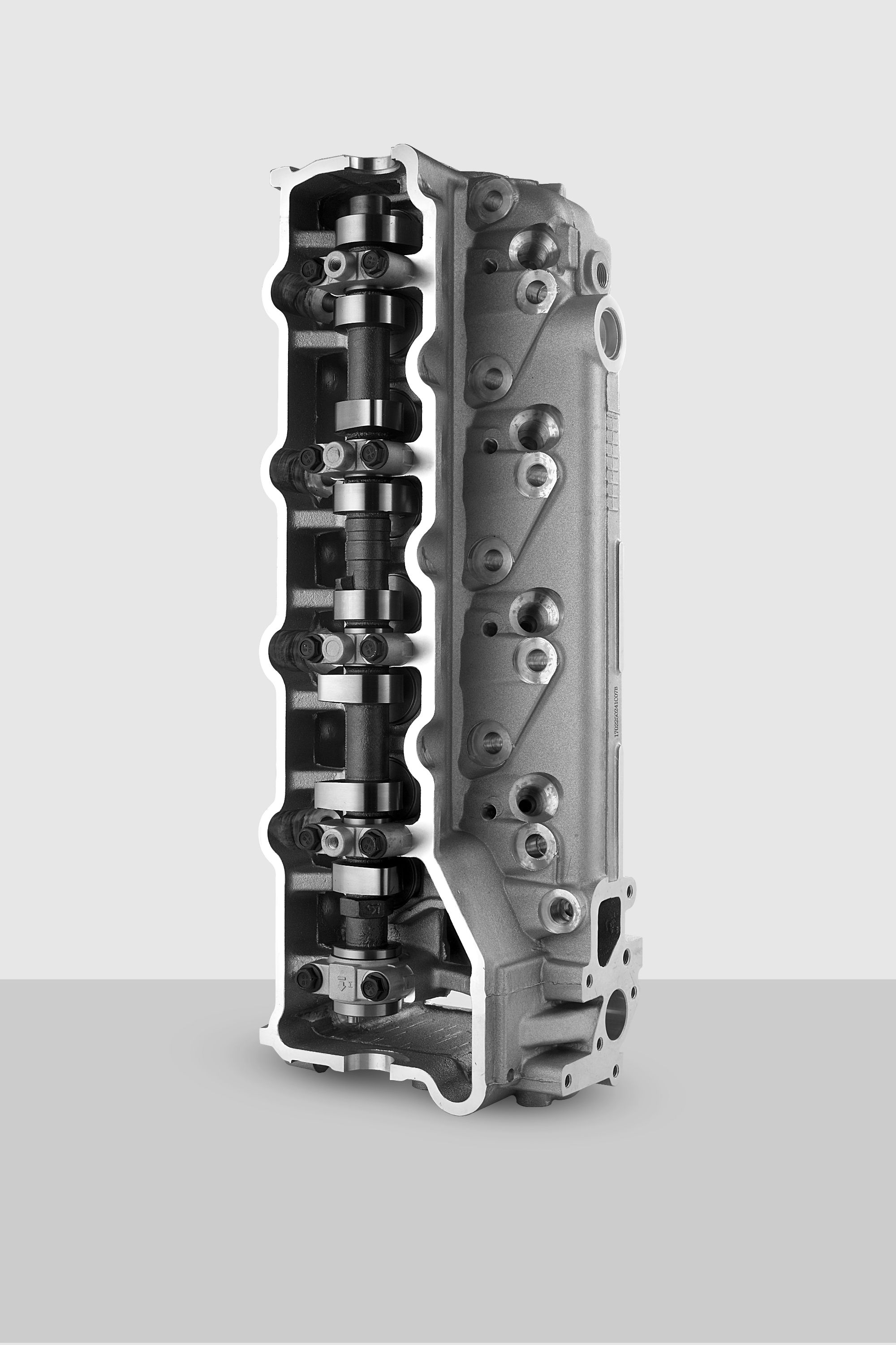
A complete assembly typically includes the casting, valve guides, valve seats, valves, springs, retainers, keepers, seals, and often the cam carrier or rocker supports. The difference between a bare head and a finished assembly comes down to whether those components are machined, fitted, and verified as a working system rather than simply bolted together.
Combustion chamber volume, valve seat depth, and guide clearance all shift how the engine breathes and burns fuel. A few thousandths of an inch of runout in a valve seat can reduce low-lift flow and hurt cylinder pressure. Precision machining keeps the chamber size consistent across cylinders, so each cylinder sees nearly identical air, fuel, and compression.
Aluminum sheds heat quickly and saves weight, but it expands more than cast iron. That thermal growth has to be accounted for in guide clearance, seat press fit, and deck flatness. Premium makers often use copper-infiltrated seats or specific aluminum alloys in high-stress areas to keep the valve job stable across heat cycles.
Look for evidence of controlled processes rather than just polished ports. Ask how they measure seat runout, whether chamber volumes are checked on every head, and whether they retain records of guide clearance and spring installed height. A supplier that can tell you the actual measured numbers for your specific heads is usually doing more than copying a port design.
CNC allows a port shape to be digitized, repeated, and gradually refined. It also improves consistency between intake runners and across cylinder pairs. The real gain is not just speed; it is the ability to hold tiny differences in bowl size and valve seat geometry that were once left to hand blending and varied from head to head.
Seat runout controls how the valve seals and how flow begins the moment the valve lifts. If the seat is not concentric with the guide, the valve lands slightly off-center, which can cause pressure loss and uneven heat transfer. A good valve job can pick up power without changing the visible port shape at all.
They focus only on peak flow at high lift. A more useful view includes low-lift and mid-lift flow, port velocity, and how stable the flow is through the full curve. Two heads can show the same peak number on a bench, but the one with better low-lift stability and more consistent chamber volumes will usually make the engine more responsive and easier to tune.
A deck that is too smooth or too rough can create sealing problems. The surface needs the right texture for the head gasket to bite into, while flatness across the entire deck matters more than a mirror shine. Precision resurfacing also keeps the cam bore and crankshaft centerline alignment in mind when the head is cut.
Conclusion
Precision in cylinder head assembly starts long before a head is bolted to a block. After casting, the first serious inspection is usually not about visible cracks or surface finish but about dimensional stability across the deck and cam journals. A slight shift in core placement can hide until the head is machined, and then every downstream operation inherits that error. Once the castings pass inspection, the focus moves to valve seat runout. Even a small amount of runout changes how the valve settles under spring pressure, producing an unpredictable seal at higher rpm and narrowing the usable power band well before peak flow numbers become relevant. From there, port finish decisions become less about making a port smooth and more about controlling the boundary layer where fuel droplets and air behave differently. A surface that looks polished may actually hurt mixture motion, while a deliberate texture can improve combustion stability without ever touching a dyno. Cylinder head assembly makers treat these choices as part of a single chain rather than isolated modifications.
Thermal cycling exposes weaknesses that static measurements miss, especially in fasteners. Builders often focus on head studs and overlook the smaller bolts around cam caps, water outlets, or accessory brackets, yet those components move through repeated expansion and contraction and can lose clamp load quietly. Guide clearance is another area where consistency matters more than peak flow. A head with excellent flow numbers but uneven guide clearance will show oil consumption and valve seat wear over time, while matched clearances keep the valve centered and the seat sealing predictably across all cylinders. The final distinction between machined heads and matched assemblies comes down to tolerance stacking. A machined head may meet individual specifications, but a matched assembly verifies that seats, guides, seals, springs, and retainers work together under load. In practice, that is where repeatable engine performance comes from, not from any single high-flow port or aggressive cam profile.
Contact Us
Contact Person: Shelly
Email: [email protected]
Tel/WhatsApp: 8613967667688
Website: https://www.yongyu.com/