
OEM Tact Switch Factory Design and Production Choices That Improve Device Reliability
2026-11-22
Every control surface starts with a switch, but not all switches survive the same way. In compact devices, the tactile switch is often the first point of mechanical failure, yet it is rarely treated as a design priority. That changes when sourcing moves from generic parts to a factory that understands how tooling, material selection, and contact geometry interact under real-world stress. KEJIAN ELECTRONICS approaches OEM tact switch production with that exact focus, turning small design decisions into measurable gains in long-term device reliability. This article breaks down the choices that separate switches that merely work from switches that keep working.
Plating Line Audits That Catch Micron-Level Drift in Tact Switches
Most plating line audits stop at the obvious: tank temperature, current density, pH. But micron-level drift in tact switches rarely announces itself through those channels. It hides in edge build-up along the contact dome, a barely visible thickening that shifts actuation force by a few grams. Our audit protocol starts by mapping the exact plating thickness across twelve points on a single switch, then compares the standard deviation against the batch's own historical baseline—not against some ideal spec sheet. That statistical approach catches a 0.3 micron drift that would pass a conventional go/no-go check.
The second layer involves looking at the plating line as a living system rather than a sequence of tanks. We pull samples every forty minutes across a full shift, not just at startup. What surfaces is often a slow thermal expansion in the anode basket or a stray current leak from a worn busbar—both of which create localized plating shadows on only one side of the switch. By correlating those physical findings with intermittent high-resistance readings from the final test, we can trace a five-micron drift back to a loose contact screw on a rectifier, something a standard audit would never flag.
Finally, we insist on cross-shift consistency. A plating line run by three different operators almost always shows three distinct drift patterns, yet most audits average them out and hide the problem. Our approach treats each shift as its own process and only merges data after confirming that drift vectors align. When they don't, the audit pinpoints the specific habit—rinse dwell time, rack agitation rhythm, even the angle at which an operator loads the barrel—that causes one shift to plate five microns heavier on the contact edge. That level of resolution turns a routine check into a tool for preventing intermittent failures before they ever reach the customer.
Solder Heat Profiles That Don't Rob Tact Switches of Click Feel
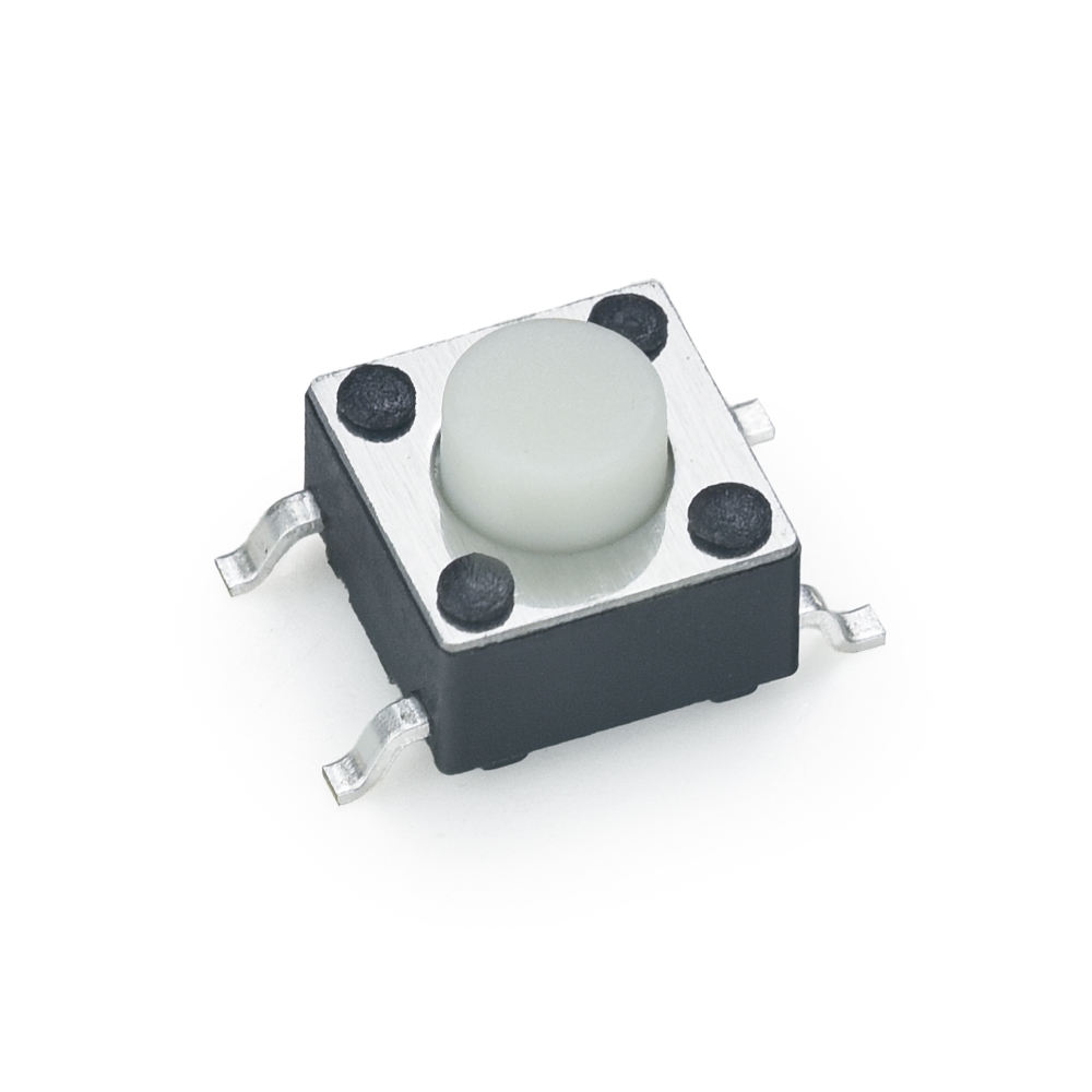
A tactile switch can leave the reflow oven electrically fine yet feel like a cheap membrane key. The usual culprit is not the solder joint itself but the heat budget the dome and contact faces absorb. When peak temperatures climb too high or the time above liquidus stretches long, thin metal domes relax just enough to lose their crisp snap, while contact plating can oxidize and add a faint grittiness to the stroke. Keeping that click alive means treating the profile as a mechanical constraint, not just an assembly requirement.
The shape of the curve matters as much as the peak. Rapid heating early in the preheat stage can warp the switch body or create uneven expansion between the base and the dome, shifting the pivot point that produces the snap. A slower, more gradual ramp through 150°C to 180°C lets the housing and internal parts normalize before the solder melts. On the back end, cooling rate is often overlooked. If the board exits too hot or cools unevenly, residual stress can settle into the switch and dull the return, making the click feel soft or inconsistent across the panel.
For lead-free SAC305 profiles, a practical target is a peak of 245°C to 250°C at the switch body, with time above 217°C kept between 60 and 90 seconds. Total time above 200°C should be held tight, and cooling should stay in the 2°C to 4°C per second range until the board drops well below solidification. Place a thermocouple on a switch body near the center of the board, not just on a bare pad, because the switch's mass can lag the board temperature. Small adjustments there usually protect the dome's temper and the tactile return far more than reworking solder joint defects later.
Cleanroom-Style Contamination Controls on the Switch Assembly Floor
Switch assembly areas are run more like microelectronics labs than typical production floors. Positive air pressure pushes airborne particles toward the exits, while sticky mats at every doorway pull debris off wheels and soles before anyone gets near a contact surface. Operators wear lint-free smocks, hairnets, and nitrile gloves, but the real discipline shows in smaller habits: tools stay on designated foam, wiping materials are sealed between uses, and even cardboard is banned from the line because it sheds fibres.
Contamination is treated as a measurable defect, not a housekeeping afterthought. Portable particle counters sample the air at shift changes, and surface swabs are checked from workbenches, pick-and-place nozzles, and fixture jaws. If counts drift upward, the response is immediate: a specific bench is isolated, tacky rollers are run over flat surfaces, and the HEPA pre-filters are inspected before the problem spreads.
Static control overlaps with cleanliness more than most people expect. Charged surfaces attract fine dust even in a filtered room, so ionizing bars are placed near feeding bowls and contact riveting stations. Grounded trays, dissipative mats, and wrist-strap checkpoints help keep particles from clinging to switch bodies, terminals, and actuator parts until the final cover is seated.
Batch-to-Batch Spring Force Tracking in Tact Switch Production
In tact switch production, spring force rarely stays identical from one material lot to the next. A new coil from the same supplier, or even a different heat number, can shift snap ratio and return force enough to change how the switch feels under a fingertip. Tracking force by batch therefore starts long before assembly: every incoming spring lot is sampled, measured, and logged against its actual force curve, not just checked against the drawing tolerance. That incoming data often shows wider drift than the supplier certificate would suggest.
The most useful tracking links force measurements to tooling condition and raw material history. Stamp tool wear usually lowers peak force gradually, while a change in plating thickness or strip hardness can push force in either direction. A simple running chart of batch averages and ranges lets engineers catch a forming station drifting toward the lower control limit before the line starts producing scrap. Adjustments can then be made to the tool or to the incoming material spec, rather than waiting for final switch testing to reveal a problem.
On the assembly side, batch force data helps separate genuine switch defects from acceptable tactile variation. If a lot sits near the upper end of the force window and field complaints describe switches as stiff, the spring batch can be traced quickly through lot codes or date stamps. Closing that loop makes the next production run easier to pre-adjust, and a supplier can be put on hold before the assembly line slows down or quality costs climb.
Designing Out Ingress Points Before Switch Tooling Begins
Sealing problems rarely start at final assembly. They start the moment a seam or a snap is drawn in a way that creates a hidden path for water, dust, or humid air. Before any switch tooling is commissioned, the housing details should be walked through as a set of possible leak paths rather than as static geometry. A boss that seems harmless can force a wall thickness change, and a clip pocket can pull a parting line somewhere difficult to control. Settling these moves early usually costs far less than adding gaskets or potting after the first parts fail an ingress test.
It helps to list every interface that will exist on the production part, including actuator openings, lens edges, cable entries, and even label recesses. For each one, ask whether the opening can be removed or moved to a less vulnerable face. Where it cannot, define the mating surfaces with enough bearing area and rigid support that the tool can hold the dimensions without heroic polishing. Vague promises of a sealant bead or a secondary operation should not be used to rescue a weak parting line; the tooling has to create the conditions for the seal to work from the first shot.
A practical review during this phase also catches trade-offs that would otherwise appear as tooling changes later. A snap that needs room to flex may sit directly under a sealing surface and undermine compression. An ejector pin location might create a small witness mark exactly where a gasket must sit. Resolving these overlaps on paper is faster than recutting steel, and it keeps the switch housing design from accumulating layers of fixes that add cost without improving reliability.
End-of-Line Duty Cycle Testing That Mirrors Real Tact Switch Use
Most endurance benches treat every cycle the same: a fixed force, a fixed rate, and a clean center press. That approach misses what happens on a real board, where an operator may hit the edge of the button, pause mid-press, or release slowly. Our end-of-line duty cycle test runs a mixed sequence drawn from actual usage records, so each unit sees off-center presses, rapid double hits, and occasional long holds instead of a sterile repetitive pattern.
The test sequence is not randomized noise. It is built from measured press profiles collected during application testing, then compressed into a repeatable script for the production floor. A programmable actuator replays those profiles while contact resistance, bounce duration, and intermittent open events are monitored continuously. Any drift beyond the acceptance window marks the switch before it can reach a customer.
The result is a duty cycle check that catches marginal plating, weak internal contacts, and early fatigue that uniform cycling would smooth over. It costs a few extra seconds per board, but it keeps the line's pass/fail decision tied to how the switch is actually used rather than a datasheet ideal.
FAQ
It usually comes down to contact plating thickness, dome geometry, and assembly contamination control. A thin silver or gold layer can wear through under micro-motion, while poor terminal flatness and uncontrolled soldering heat create latent solder joint cracks.
Crispness comes from the snap characteristics of the metal dome and how evenly the housing supports it. If mold cavity pressure and injection parameters drift, dome preload changes and tactile response becomes inconsistent, so stable factories control those variables and often run inline force sorting.
Plating affects oxidation, fretting corrosion, and arc erosion more than basic conduction. Gold resists corrosion but can suffer adhesive wear, while silver is cheaper but prone to sulfide tarnishing. Many designs use selective gold or silver-nickel composite plating to balance environmental tolerance and mechanical life.
A steeper force-displacement curve and controlled return travel help the dome snap past its trip point quickly instead of hovering near it. Production-side sorting of dome hardness and consistent preload are just as important, because small variations let the contacts bounce open under vibration.
If the terminals are not on the same plane, some may float or get stressed after placement, causing cold joints or micro-cracks after reflow. Reliable stamping lines add a flattening step and then check terminal height with laser or vision systems, usually keeping variation under 0.1mm.
The main risk is the path along housing seams and terminal exits. Ultrasonic welding or two-shot molding closes those gaps, while overmolded terminals or sealant at the lead-out area stop moisture wicking that can form insulating films on contact surfaces.
Automation reduces skin oils, sweat, and static damage from manual handling, and it keeps dome placement, lubrication amount, and housing pressing force repeatable. Manual lines tend to show wider batch-to-batch variation in those areas, which later appears as scattered cycle life data.
Look at whether the test conditions match the real load, temperature, humidity, and switching rate. More useful signs are failure distribution over time, contact resistance drift curves, and solder joint shear results, not only a single maximum cycle count. Batch-level life sampling also tells you more than a one-time qualification report.
Conclusion
Reliability in OEM tact switches rarely hinges on a single dramatic fix. It accumulates from small manufacturing decisions, like running plating line audits that catch micron-level drift before contact resistance becomes a field problem. On the assembly floor, cleanroom-style contamination controls matter just as much as the plating itself; a stray particle trapped under a dome can turn a crisp click into an intermittent contact. Early design work also plays a quiet role. By designing out ingress points before switch tooling begins, factories avoid retrofits that weaken housing integrity and let moisture or flux reach the contacts later.
Thermal handling is another area where reliability can slip away. Solder heat profiles tuned to avoid robbing tact switches of their click feel help preserve dome geometry and tactile response after board attach. Batch-to-batch spring force tracking then keeps actuation force consistent, so devices feel the same across production runs and do not drift toward premature wear. Finally, end-of-line duty cycle testing that mirrors real tact switch use catches units that pass simple continuity checks but would fail after repeated presses. Together these choices form a factory-level discipline: catch tolerances early, protect the mechanism during assembly, and verify behavior the way the end product will actually use it.
Contact Us
Contact Person: Anna lin
Email: [email protected]
Tel/WhatsApp: +86 13567768885
Website: https://www.kjele.com/